Task step
The task step is a basic building block of the integration task. Every task step is linked to a connector - a dynamic link library .dll i.e. a key program in the integration process. Depending on the selected connector, the input and output schema, and configuration(s) are preselected in the task step.
You can learn about the Task Step feature by watching a detailed video or reading the written documentation below. Choose the approach that fits your learning style bes. Watch the visual guide to quickly grasp the main concepts, or explore the step-by-step instructions for in-depth detail. Both formats help you effectively understand and use the Task Step feature in Integray.
Task step editor
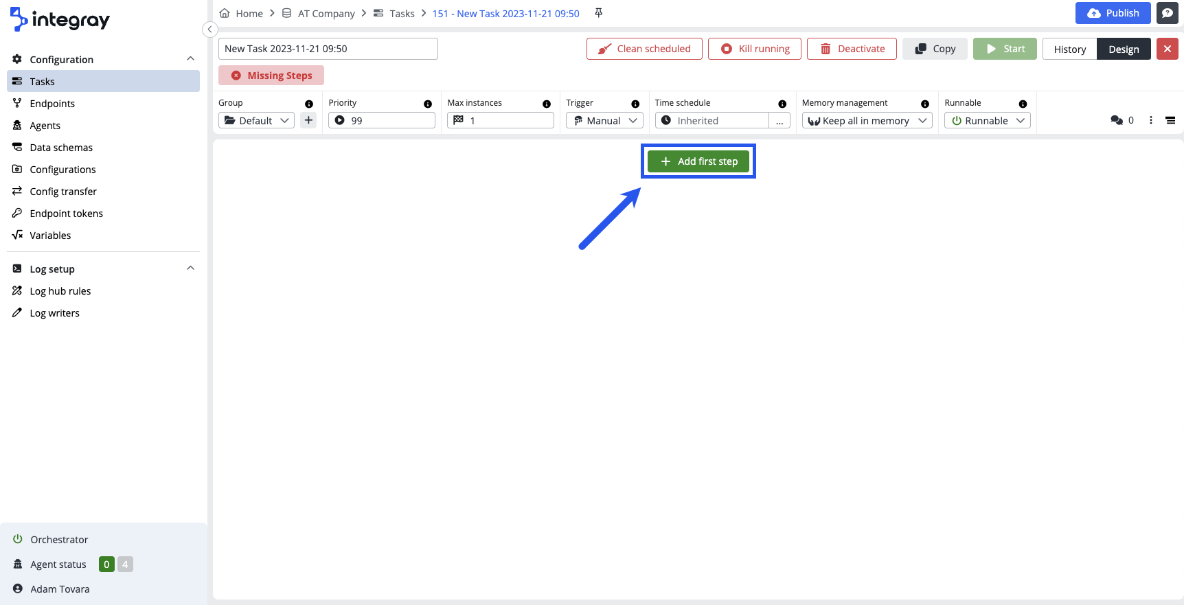
Open the Task design editor and start creating your first task step with the green button + Add first step.
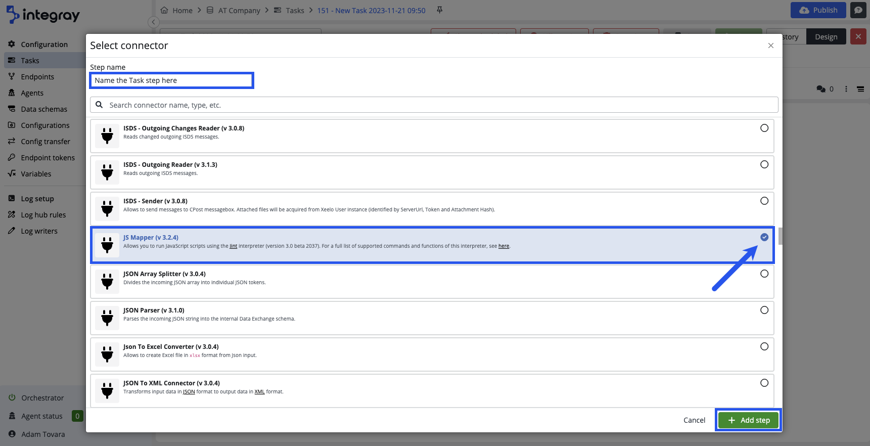
Click the button opens the modal dialog window Connector settings, where the user must select the required connector for the first task step.
The Select connector settings modal window consists of:
-
step name - enter the name of the step
-
full-text search
-
catalog of available connectors
To use the selected connector from the list of connectors displayed in the modal window, check it (with the check button on the right) and click the green + Add Step button to create the first step, including the connector.
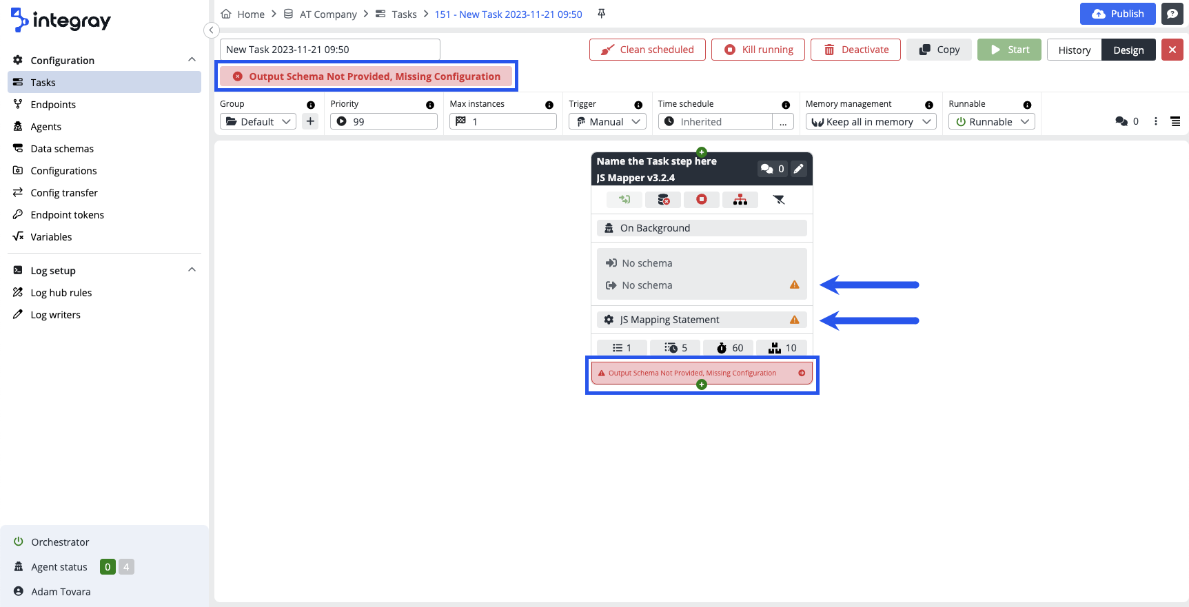
The first task step is displayed on the Task editor. The task step is not configured yet, therefore red warning messages are displayed on the task header as well as on the task step.
The error message displayed on the image may differ based on the selected connector, nevertheless it will always inform you what is missing. You also will see the amber triangel with exclamation mark icons there, where the configuration is missing.
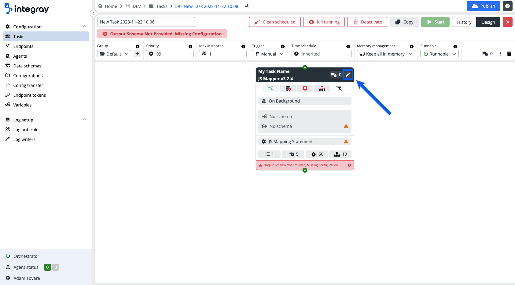
To open the Task step editor and start the task step configuration click on the pencil icon in the top right corner of the task step.
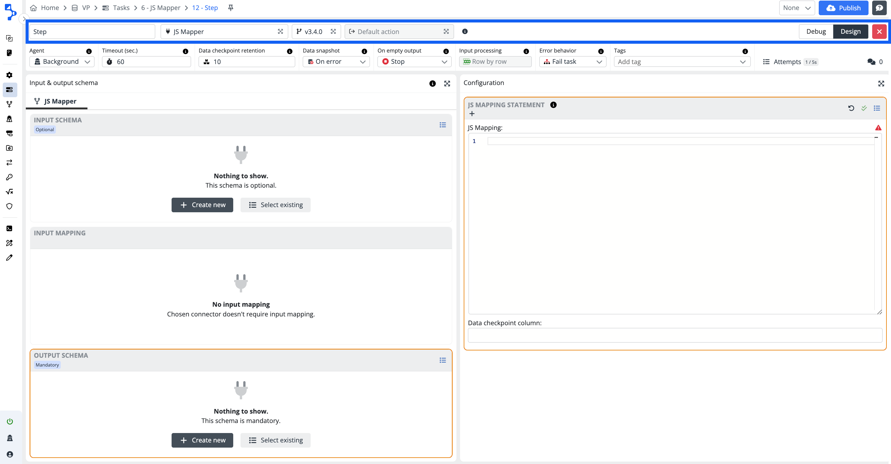
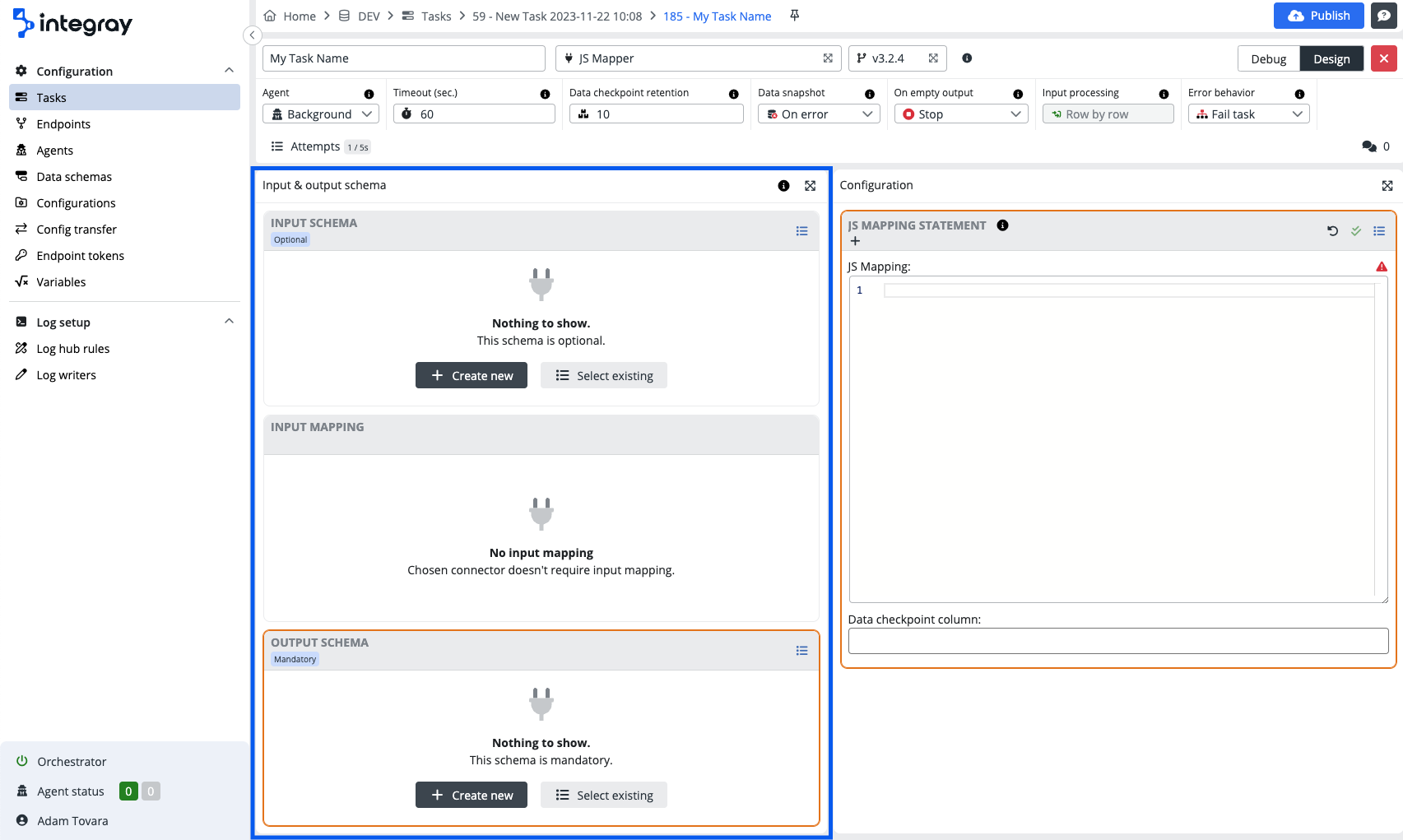
The Task step editor consists of the following parts:
Be aware, that not all parts are active and used in case of every connector. The use of the respective task editor parts is connector dependent.
Step title header
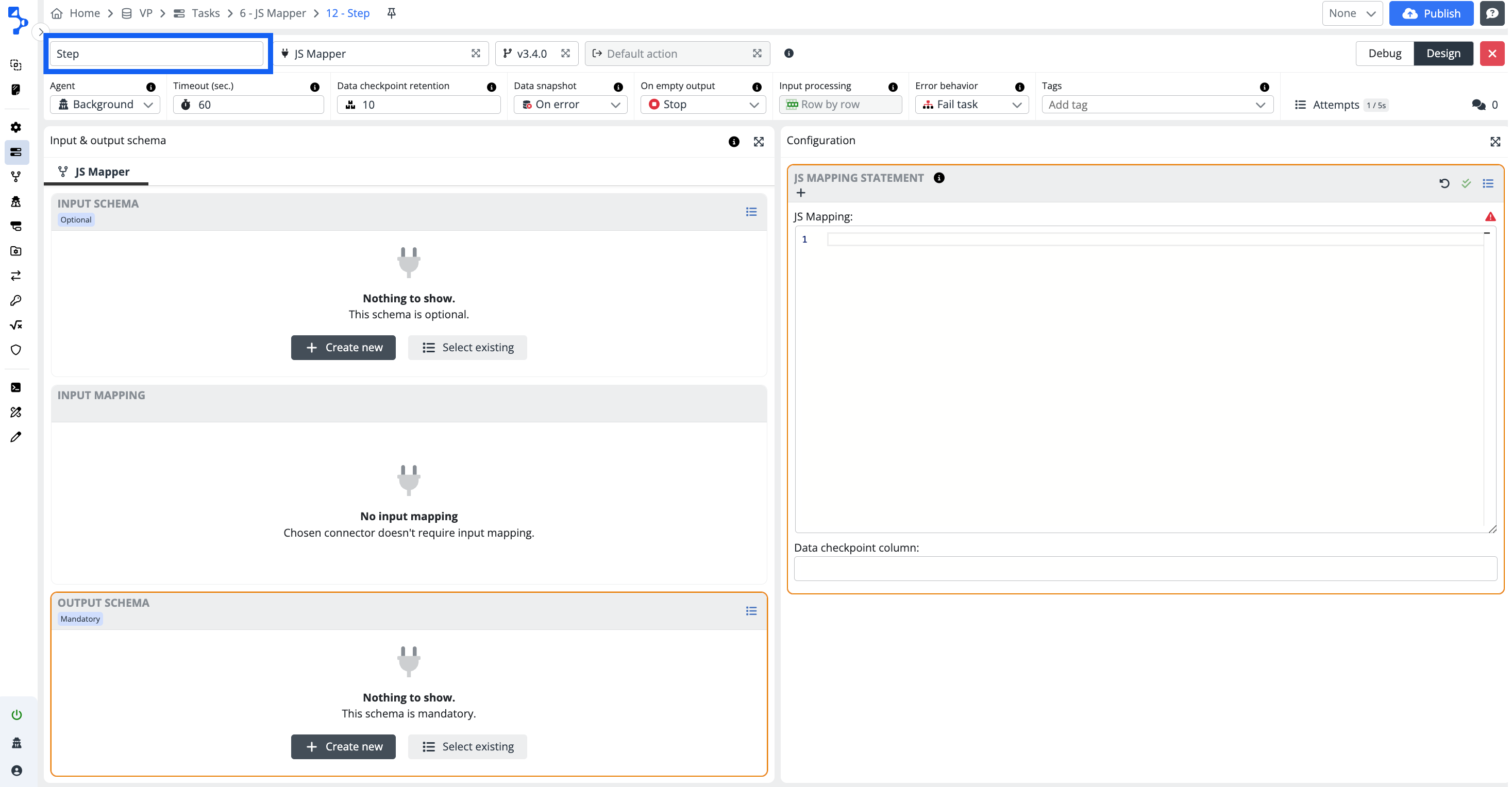
Task step name
The task step name describes the task and is displayed on the header of the task step. The default value of the task step name is Step #< sequence number >. Replace the default name with a specific name with a purpose. This helps to describe and understand the process step. You can also see the task step name including its ID in the breadcrumbs bar at the end.
Connector
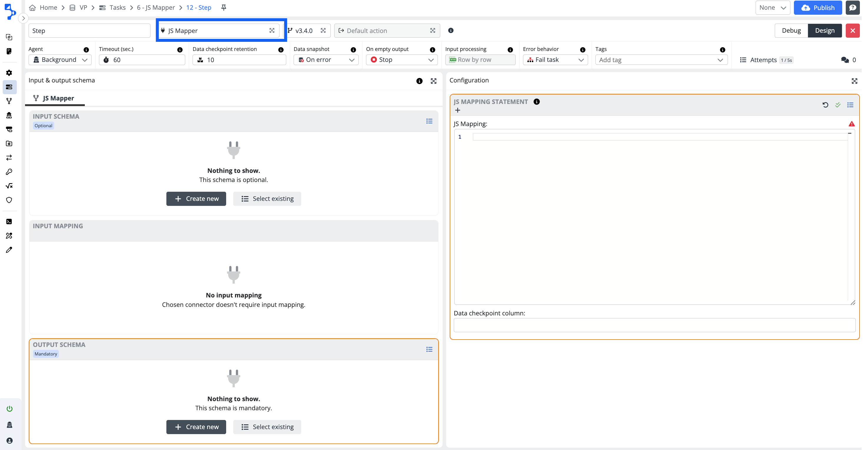
The connector is a dynamic link library .dll i.e. a key program in the integration process. It is a program, which receives data from the source in connector specific structure and translates it into an understandable structure and format for the next destination. Based on connector type, there are input data schema, and configuration, output data schema panels available within the task step.
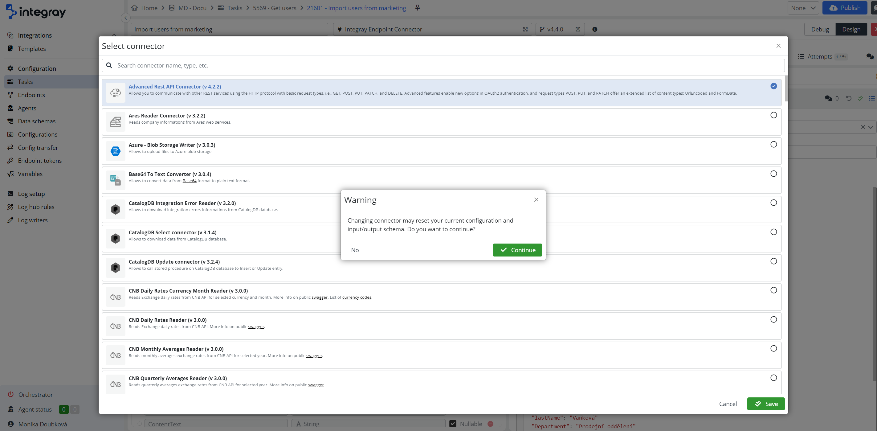
If you decide to change connectors, you will be asked to confirm the connector replacement.
Changing connector may reset your current configuration and input/output schema
Always assess impact of the connector change, before change itself.
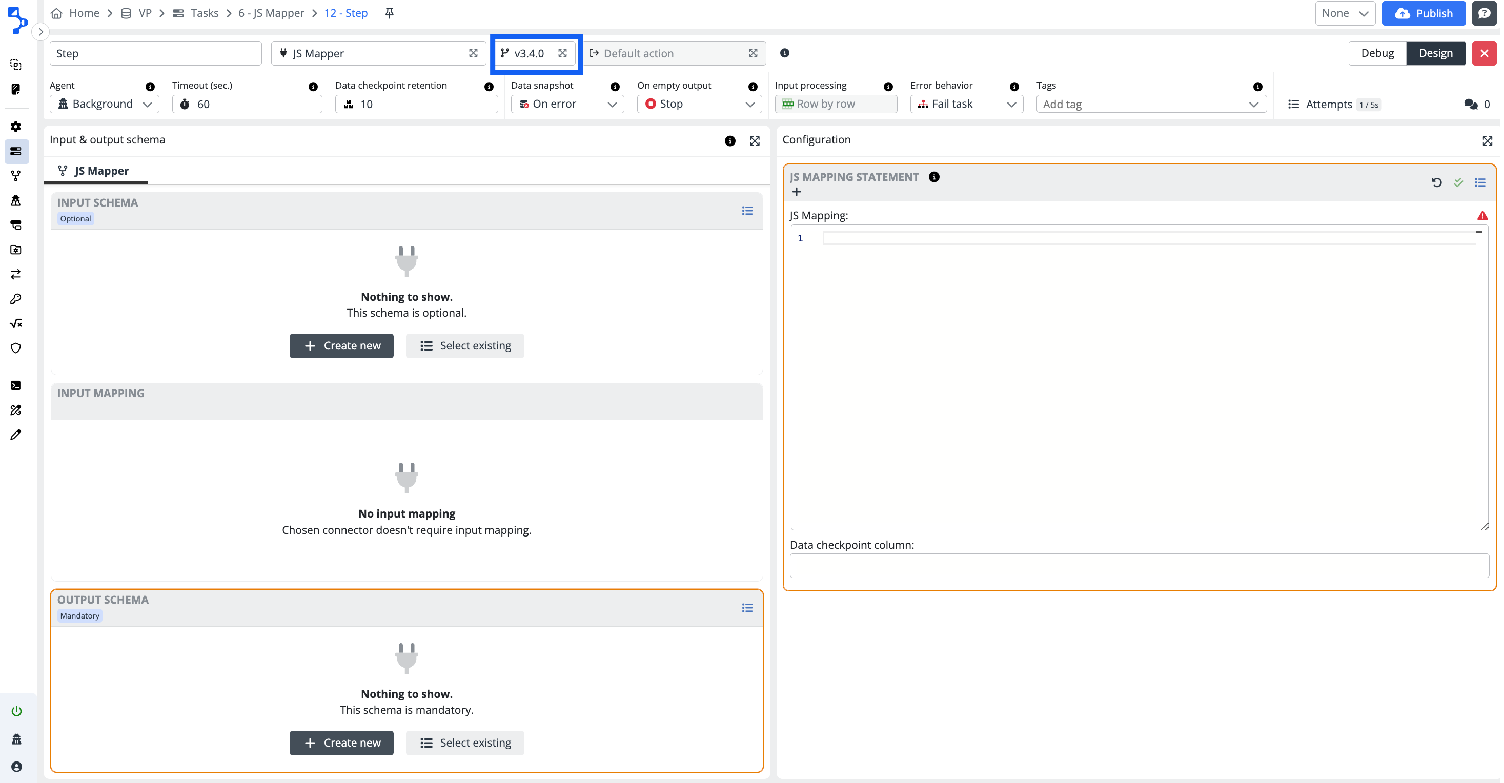
Connector version
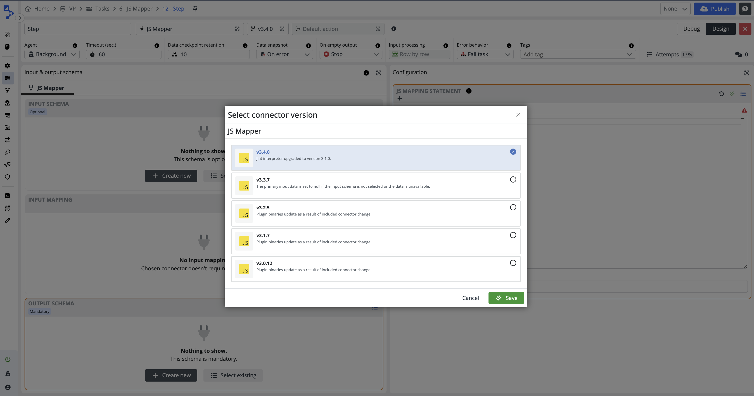
The connectors are constantly being reviewed and improved to offer the best possible value to the users. As a result of updates, the connectors may have more than one version of the connetor available.
Click on the field with the code-branch icon and the connector version number to view all available connector versions.
When you select the connector when configuring new task step, the offered and chosen version will always be the latest available at the time of the configuration.
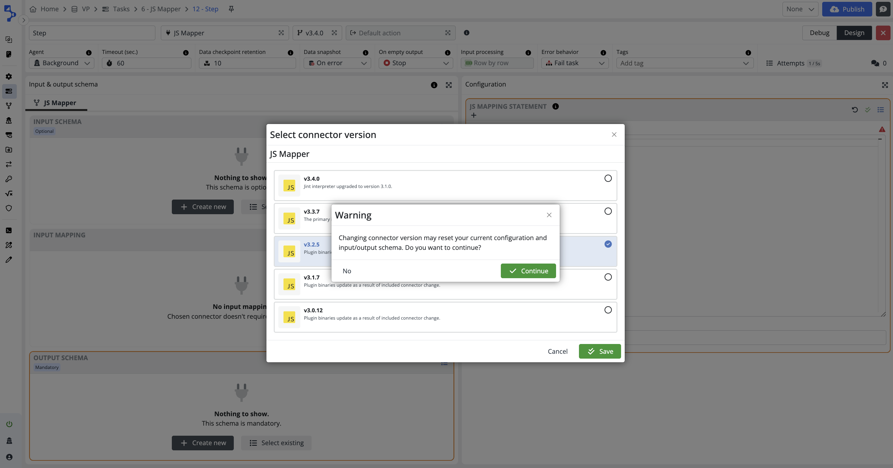
If you decide to change connector version, you will be asked to confirm this decision.
Use the latest version when configuring new step
It is strongly recommended to use the latest available connector version when you configure new task step.
On the other hand do not change connector versions in existing configurations when a new version appears. Always assess impact of the version change, before change itself.
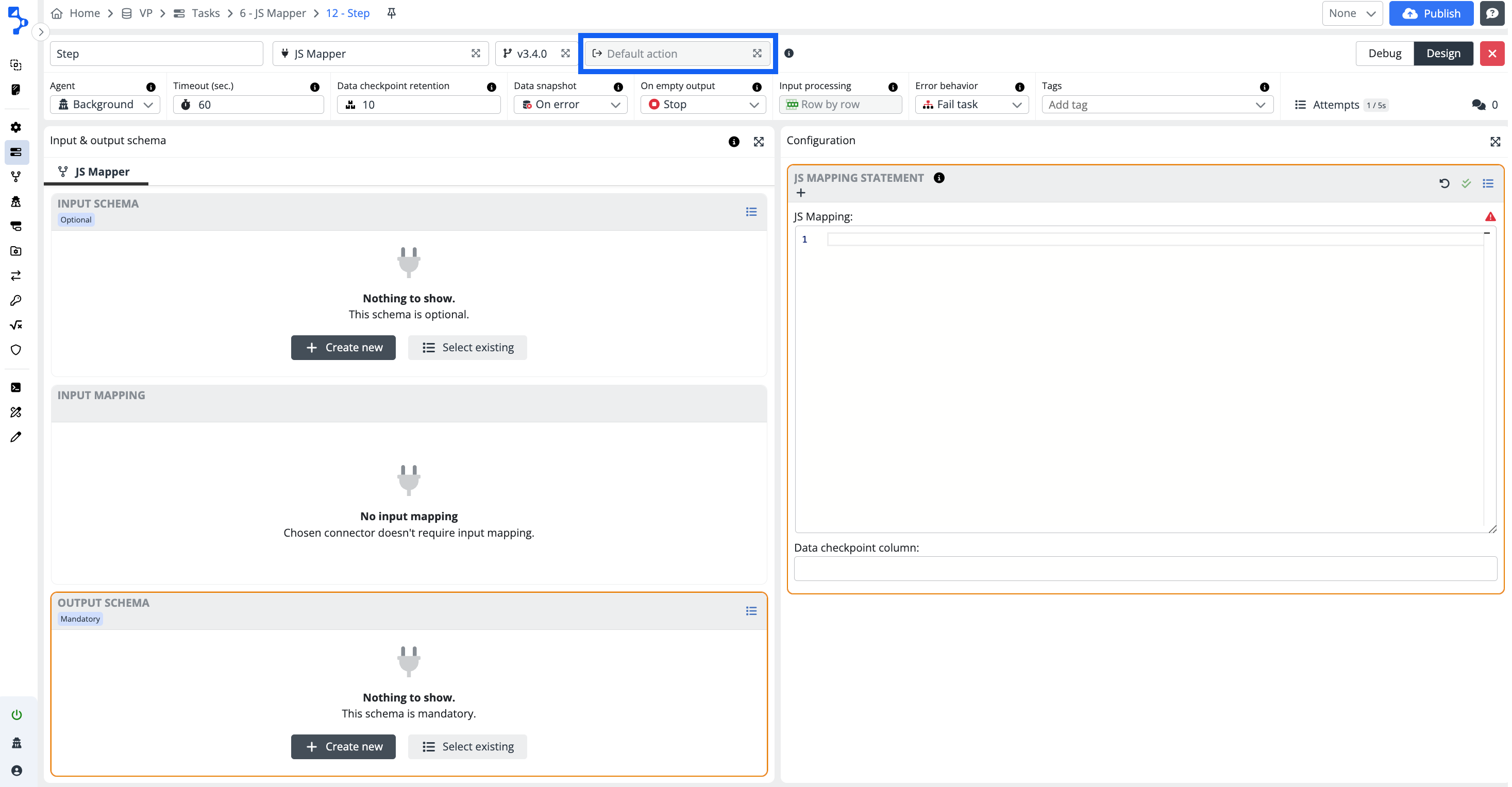
Connector actions
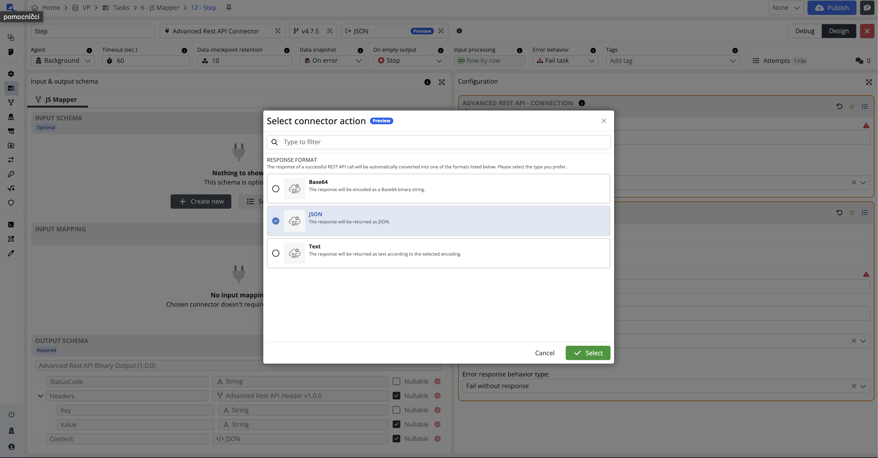
This feature enables the selection of the connector action for connectors that support multiple actions. When the desired action is selected, the system automatically adjusts the configuration, input, and output schema to align with the required connector settings.
This enhancement streamlines the process, ensuring users can achieve the desired results without manually adjusting the connector settings.
Debug mode
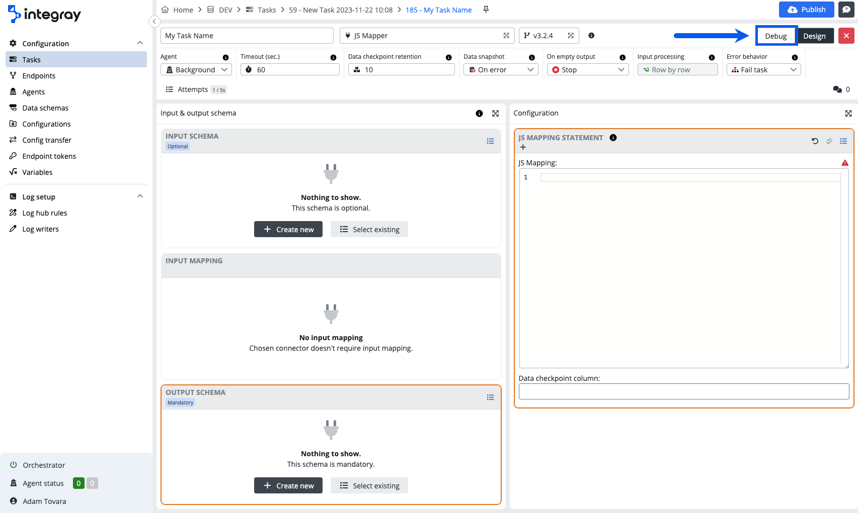
The switch between the Design view mode and the Debug mode. The debug mode allows you to debug your specific configurations.
Close
Use the red square with cross close button to exit the task step editor detail configurations.
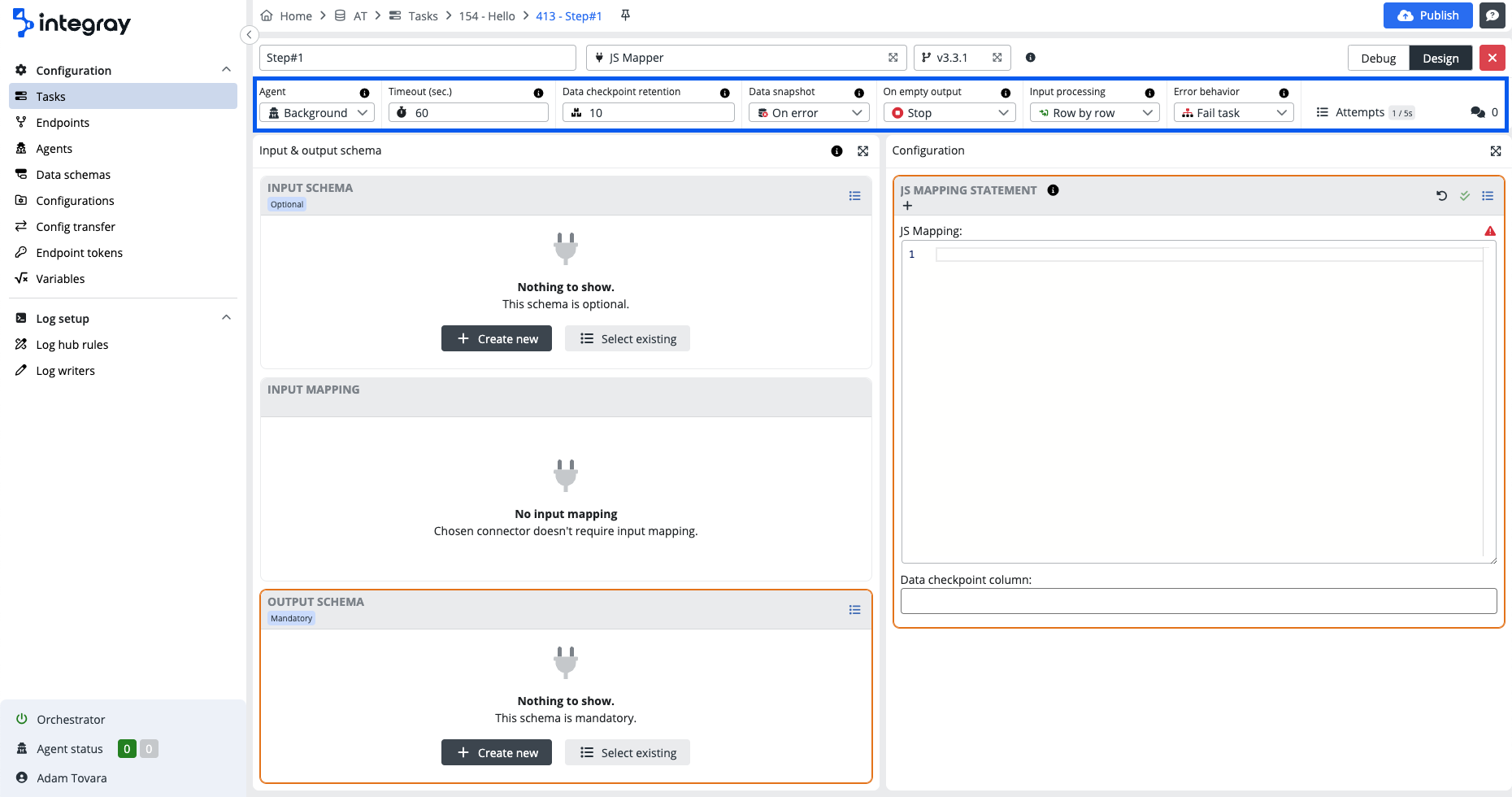
Step configuration header
Agent
Select the agent to be used to serve this task step. Default value is set to Background agent. The background agent is a platform agent available and ready to serve any task step not reaching out for remote resources. Select the appropriate remote agent to serve task steps reaching out for external/remote resources. The valid principle - use the agent who is installed in the same environment as the resources served.
Timeout (sec.)
The timeout period (in seconds) defined for the task step. If task step execution lasts longer, the step will fail and will follow configured error behavior.
Data checkpoint retention
Connectors are designed as stateless functions. However, for keeping necessary data, such as list of processed items, they can use a data checkpoint. It is a simple key-value database kept for each task step separately. Data checkpoint retention option represents number of versions of stored data which are kept before gets deleted. Higher number of versions can waste internal database storage space, but enables more options to turn back in history of processed data. The option starts a modal window enabling the modification of the data checkpoints for the task step.
Data snapshot
The condition, under which the data structure will be stored in the database. The data structure is accumulated sequentially, so the structure that was created by concatenating the output of the current step and all previous steps is always stored in the database.
-
Never - The data structure will never be stored.
-
On error - The data structure will be saved only in case of a step failure.
-
Everytime - The data structure will be saved every time.
Use of the data snapshot setting Everytime
Do not use the option Everytime in a production environment due to large amounts of data generated resulting in increased size of the data file and to avoid any potential performance issues.
On empty output
Prevents executing the next step if the current step doesn't produce any output data.
-
Continue - The task will continue with the next steps regardless of whether the step has produced any data or not.
-
Stop - The execution of the current task branch will be stopped.
Input processing
The defintion of the data processing mode. Data received on the input side can be further processed:
-
Row by row - Input data processed by single rows/records.
-
Bulk - Input data processed as bulk.
Processing types
Be informed that the platform connectors can process the input data above mentioned ways i.e. Row by row, Bulk, or Both. In the connector academy, every connector does indicate its allowed process type as well as the default set process type in the case when both types are allowed.
Be mindful of implications when you decide to change the processing type from the default one to the alternative one. Always consider the integration scenario and set the processing type based on it.
Step run status codes
List of status codes associated with the execution of steps within a task run. These status codes can be used to monitor the progress and outcome of individual steps within a task run, facilitating effective troubleshooting and management of workflow processes.
| Status | Description |
|---|---|
1 - Scheduled |
The step is scheduled for execution but has not yet begun. |
100 - In Progress |
The step is currently being executed. |
101 - Waiting For Agent |
The step is awaiting connection with an agent for execution. |
200 - Finished Success |
The step has completed successfully without any errors. |
201 - Finished No Data |
The step has finished successfully, but no output data was generated. |
203 - Nothing To Process |
The step has finished successfully, but there was no data to process. |
300 - Failed Connector |
The step failed due to issues related to input/output schema or connector configuration. |
302 - Failed Timeout |
The step failed due to exceeding the maximum duration allowed for execution. |
303 - Failed Cancelled By User |
The step was canceled by the user during execution. |
401 - Not Run |
Indicates that the step was not executed because the task run was stopped prematurely. |
Error behavior
Determines how the task behaves when the step fails.
-
Fail step & continue and Fail task & continue options continue executing the task regardless of the status of the step.
-
Fail step and Fail task options immediately terminate the execution of the task in the current branch. Other branches will finish according to their settings and then the status for the task run will be evaluated.
-
The Fail step and Fail step & continue options do not propagate the error status to the task run level. The run is still considered successful (status 2xx), but it is marked as having ended with an error: 202 - FinishedWithErrors.
-
The Fail task and Fail task & continue options promote the error status of the step to the task run level. The step is considered failed (status 3xx) and its status will be the same as the failed step status.
| Error behavior | Task run status | Continues execution |
|---|---|---|
| Fail step | 202 - FinishedWithErrors |
No |
| Fail task | Step status e.g. 300 - FailedConnector |
No |
| Fail step & continue | 202 - FinishedWithErrors |
Yes |
| Fail task & continue | Step status e.g. 300 - FailedConnector |
No |
Attempts
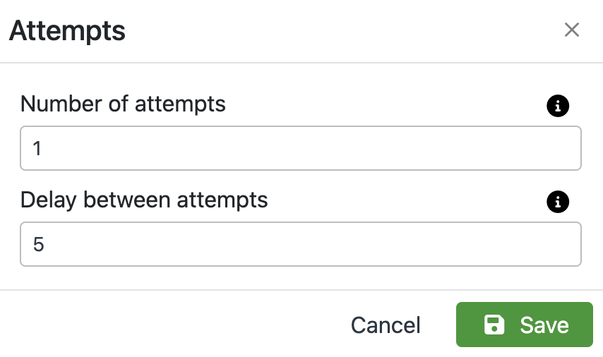
Maximum number of connector failed executions before the step is marked as failed. In case of unexpected unavailability of integrated systems, meaningful setup of attempts and attempt delay (delay in seconds between particular attempts) may support the successful completion of a task step if the availability resumes again within the period of the defined attempts. By increasing the number of attempts and choosing a suitable delay between these attempts, communication with the external system can be repeated after a while. In case of temporary unavailability, the integration task can be successfully completed.
Comments
The comments option provides you with a tool to document important points related to the task. It may be the detailed purpose of the task, what it does, how it is configured and why. It's up to you if and how you will use this option.
Click on the double bubble icon to enter the comment option. The modal dialog window named as the task will be displayed. The comments option works with the rich text editor i.e. your comments can include formatted text, tables, links, images, etc...
Created comment will be recorded with a timestamp. The author of the comment can edit and or delete the comment. Multiple comments are allowed for one task.
Input & Output editor panel
Input schema
Definition of the input data schema for the task step. Input schema defines the structure of the data that will be passed to the connector for processing. Such schemas can be created by the user or forced by the connector itself. Regardless of the structure itself, connectors define the following four types of input data: Optional, Mandatory, Required and None.
Optional
The selected connector does not expect a specific schema. The required data structure can be achieved by correct configuration. Although the selected connector doesn't require schema generally, the individual integration task step may need to match the output data structure of the preceding task step and use a data schema selected from the repository or create a new input schema.
Example: JS mapper connector - This connector can be used without input schema and produce data using the configuration options, nevertheless can also receive data from another source or from another step where it is required to match a specific data structure.
Mandatory
The selected connector requires mandatory input data schema, which must be selected by the user from the existing data schema repository or a new one must be created.
Example: CSV Serializer - The connector will fail without structured data.
Required
The selected connector expects a fixed data structure, otherwise, the connector will fail. It is not possible to modify the required schema for the connector or create a new one.
Example: Base64 to text converter - Required input of data in format base64.
None
The selected connector does not require data schema and does not allow to process any data input.
Example: Delay - The connector does not require data schemas as it serves a different purpose. It delays the integration process irrespective of the processed data.
Select existing schema
The input schema can be selected from the existing catalog of data schemas or can be created as a new configuration.
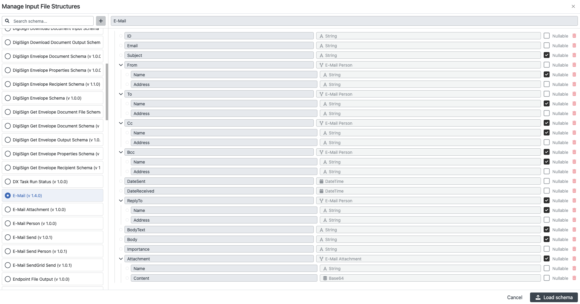
The button Select existing navigates you to the modal dialog window Manage input file structures and offers you the list of existing schemas on the left side.
There are four predefined views to facilitate your search of the relevant schema:
-
Recent - This view provides you with the list of recently used schemas in the task or schemas used in the input or output configurations of bound endpoints. It is highly likely, that you will need to use these schemas in the next configurations within the same task.
-
All - This view provides you with a complete list of the schemas including the system schemas and the custom schemas.
-
Custom - This view provides you with the list of custom-created schemas only.
-
System - This view provides you with the list of system schemas only.
When you select the input schema from the catalog, the schema structure will be displayed in the right panel. Click the button Load the schema to apply the selected schema to the configured integration task step.
Create custom schema
Click the + plus button, to the right from the schema search field and create a new custom input data schema, suitable for the connector in the configured integration task.
For a detailed description of how to "Create new data schema" go to: Help center > Configuration screen > Data schemas.
Once you are finished with your new schema, save it by clicking on the green button Save in the top right corner of the modal window, and in case you want to use it on the integration step, load the schema.
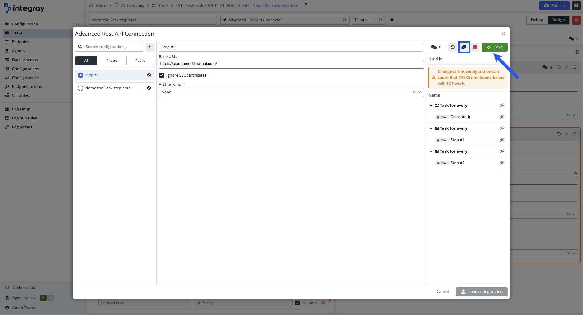
You can use the copy functionality to create your custom schema from an existing schema. This is useful in case you need to modify the existing schema and add or remove schema fields, but don't want to recreate the existing schema from scratch.
Multi input step
In scenarios where you need to incorporate inputs from multiple steps within your input schema, utilize the Multi input step feature. This functionality enhances data integration workflows by allowing the synchronization of branch inputs and the efficient management of parallel data inputs. It streamlines the complexity of managing inputs from divergent sources, improving scalability, parallel processing capabilities, and system responsiveness.
Input mapping
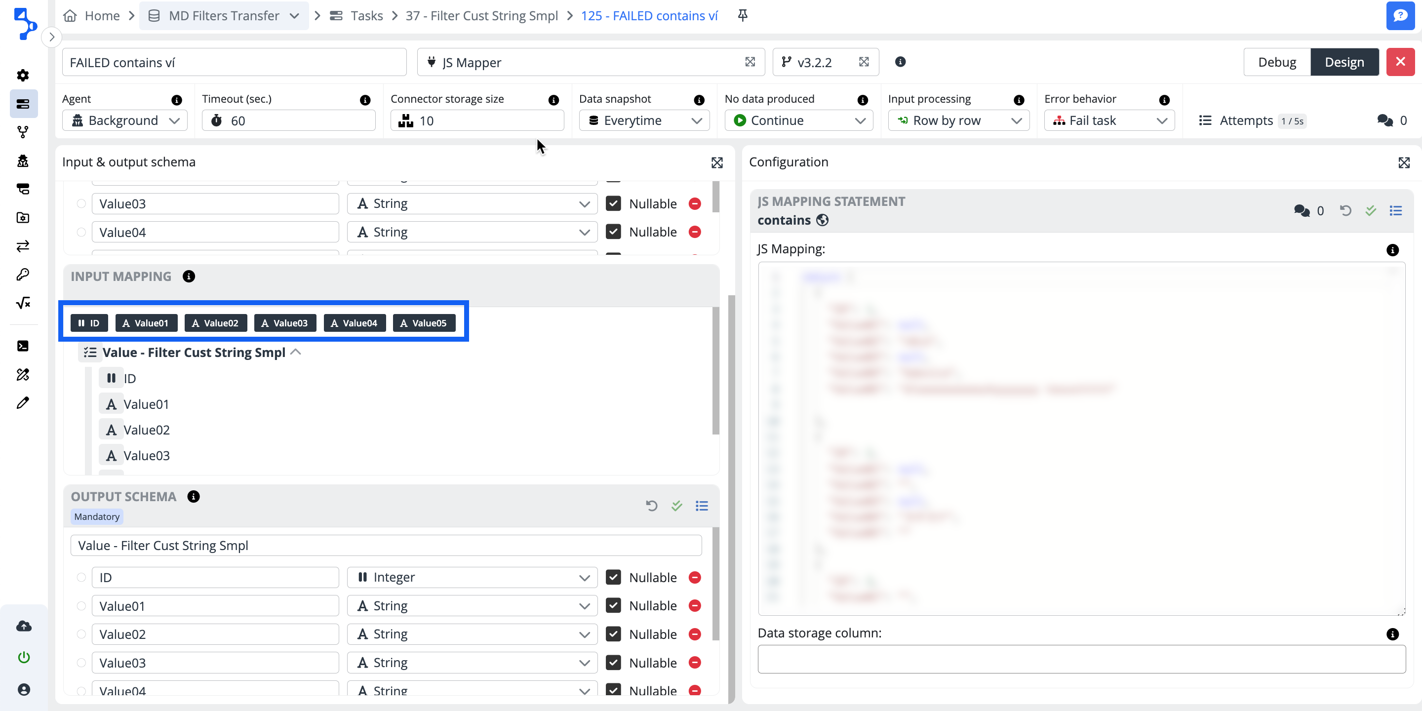
While the input schema defines the structure of the input data, the input mapping defines its content. The purpose of input mapping is to map the columns of the input schema to the elements of the data structure of the data source. At the task step start, the input data collection is created according to the defined rules and passed to the connector for processing.
Mapping
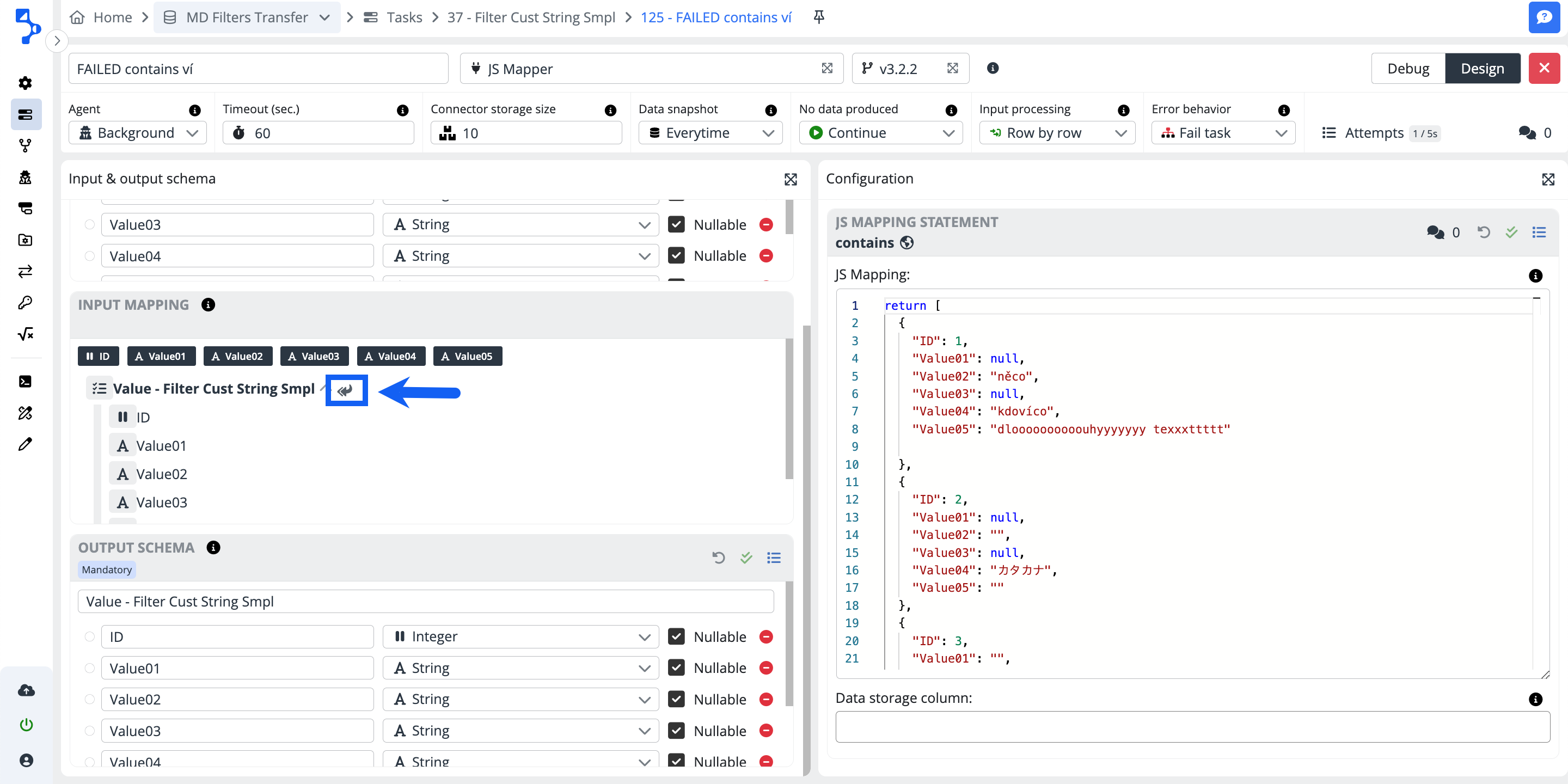
After you selected or created your input schema, use the feature of automatic mapping by clicking on the double left arrow button. The automatic mapping feature will try to pair the same named columns of the input schema with the corresponding data structure elements.
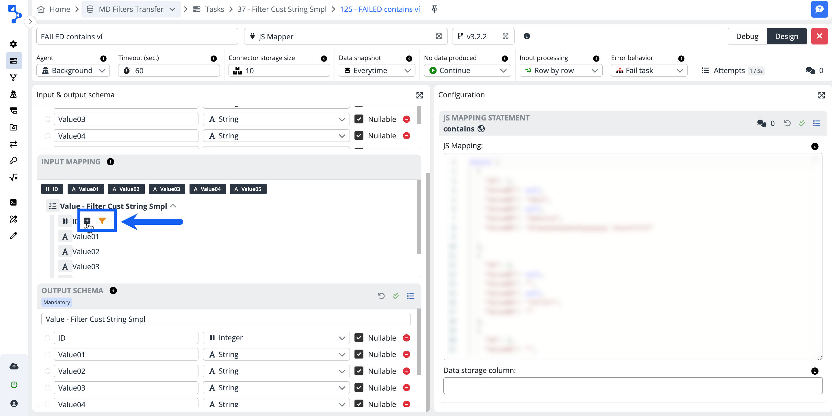
If you want to map your elements selectively, click on the small plus + button at the end of each mapping line you want to map and assign the data structure element to the individual columns of the input schema.
If necessary, add a data filter using the funnel button.
Warning
Please note, that the icons mentioned above (plus, double left arrow, and funnel) will only be visible when you hover over the nodes or leaves of the mapping tree.
Mapping filter options:
Use the orange funnel button to filter the values in the input mapping. There are different options of operators available for different column data types.
If the filters are applied for more than one mapping line the logical operator among the lines is AND.
If there are more filter conditions applied within one mapping line the logical operator among the lines is OR.
Data types and available operators
| Double, Integer, Decimal | DateTime | String | Bool | Base64, JSON |
|---|---|---|---|---|
| equals | equals | equals | is true | empty |
| not equals | not equals | not equals | is false | not empty |
| greater than | greater than | contains | empty | |
| less than | less than | not contains | not empty | |
| greater or equals | greater or equals | in | ||
| less or equals | less or equals | not in | ||
| in | between | empty | ||
| not in | not between | not empty | ||
| between | empty | |||
| not between | not empty | |||
| empty | ||||
| not empty |
Note
empty - null or ""
in and not in - input - comma separated values;
between and not between - input must be 2 values;
is true and is false - no input;
Warning
Be informed that warning message will be displayed when mapping filter is applied and the task step has set "Continue" on empty output.
Output schema
The Output schema defines the data structure that will be created by the connector when processing the data. Such schemas can be created by the user or forced by the connector itself. Regardless of the structure itself, connectors define the following four types of output data:
Optional
The selected connector does not expect a specific schema. The required data structure can be achieved by correct configuration. Although the selected connector doesn't require schema generally, the individual integration task step may need to match the output data structure of the preceding task step and use a data schema selected from the repository or create a new input schema.
Mandatory
The selected connector requires mandatory output data schema, which must be selected by the user from the existing data schema repository or a new one must be created.
Required
The selected connector expects a fixed data structure, otherwise, the connector will fail. It is not possible to modify the required schema for the connector or create a new one.
None
The selected connector does not require data schema.
Info
Selection of existing output schema or creation of a new custom schema works for Output schemas analogically as for input schemas. For details, refer to the chapter Input schema.
Configuration editor panel
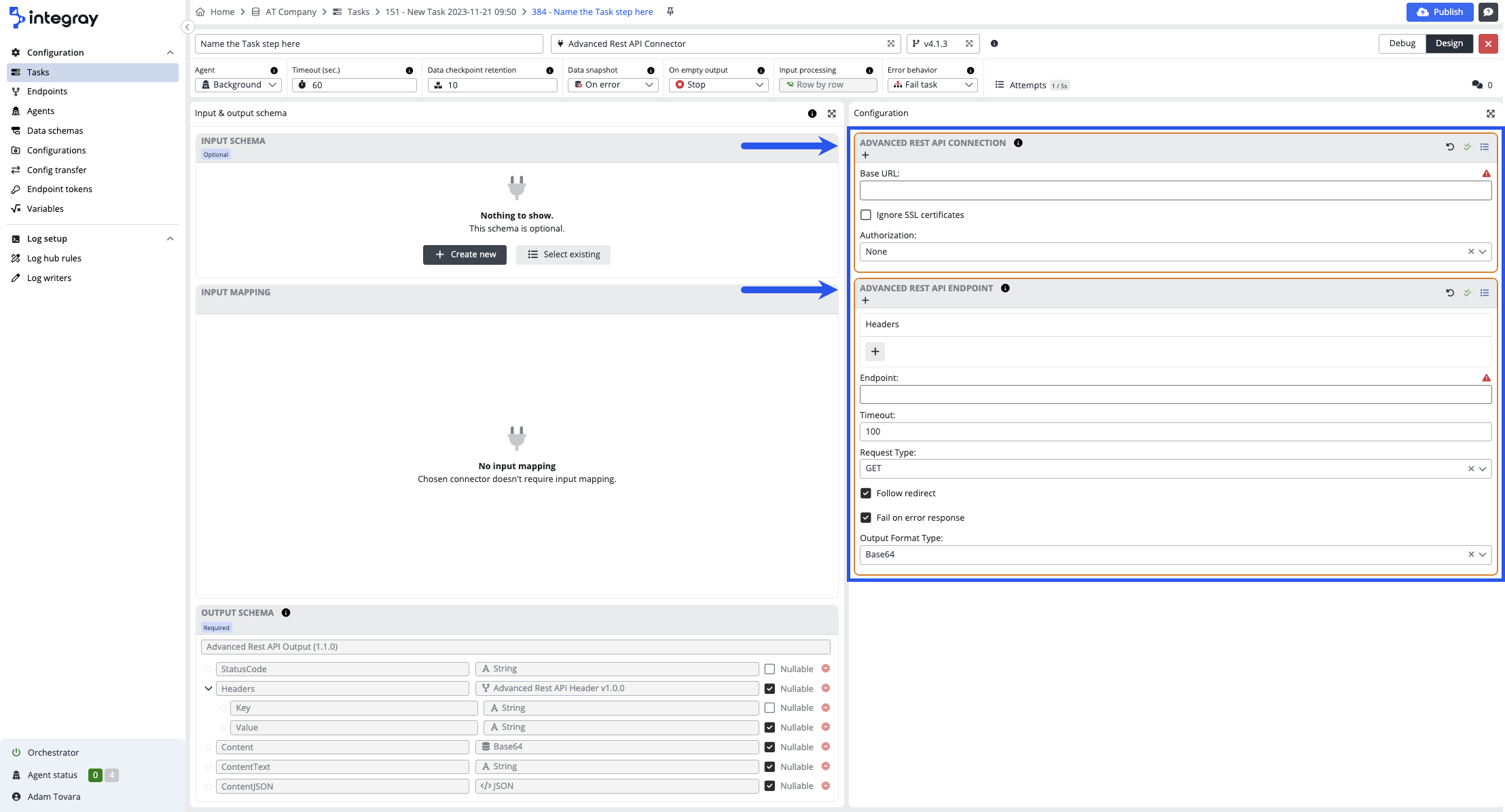
The layout of the editor panel differs based on the selected connector. Considering the editor panel, there are two types of connectors available in the repository:
Connectors with configuration
The configuration editor can include one or more configuration sections. Each configuration section represents a specific configuration. Configurations can be named and saved. Various configurations of the connector can be defined and saved. Saved configurations the platform stores in the Configurations.
Example: REST API connector - This connector consists of 2 configuration sections:
-
REST API connection - a section where the Uri and Authorization are defined
-
REST API endpoint- a section where headers, endpoint, timeout, method, data content type, and output format type are defined.
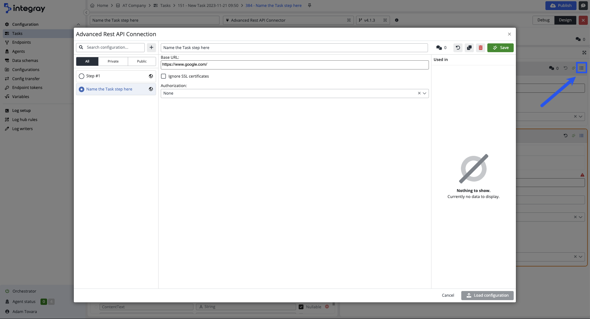
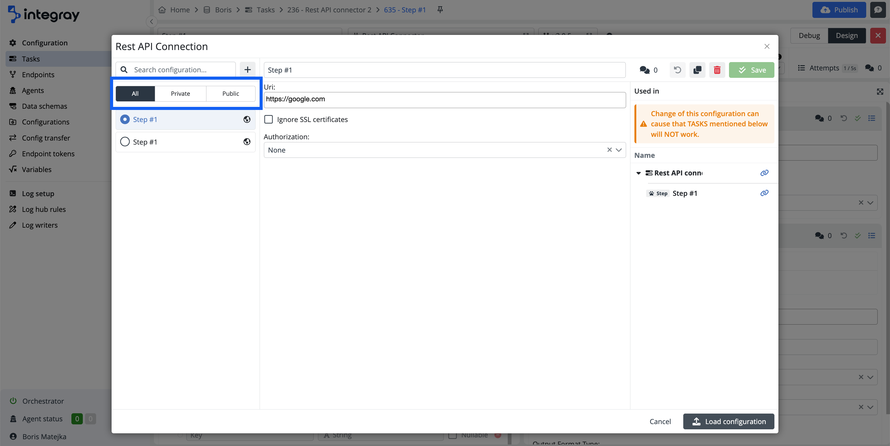
Click the bulleted list icon on the individual configuration header in the top right corner and open the modal dialog window with available configurations.
The configuration modal dialog provides extended options of work with configurations:
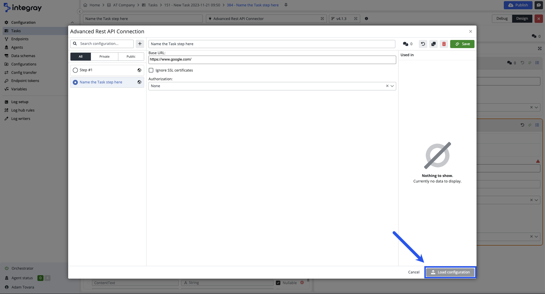
- To select a suitable configuration from the list of existing configurations and load it into the task step.
- To filter between public, private, and all configurations.
- To create a copy from the existing configuration, modify it, and save it as an additional in the list,
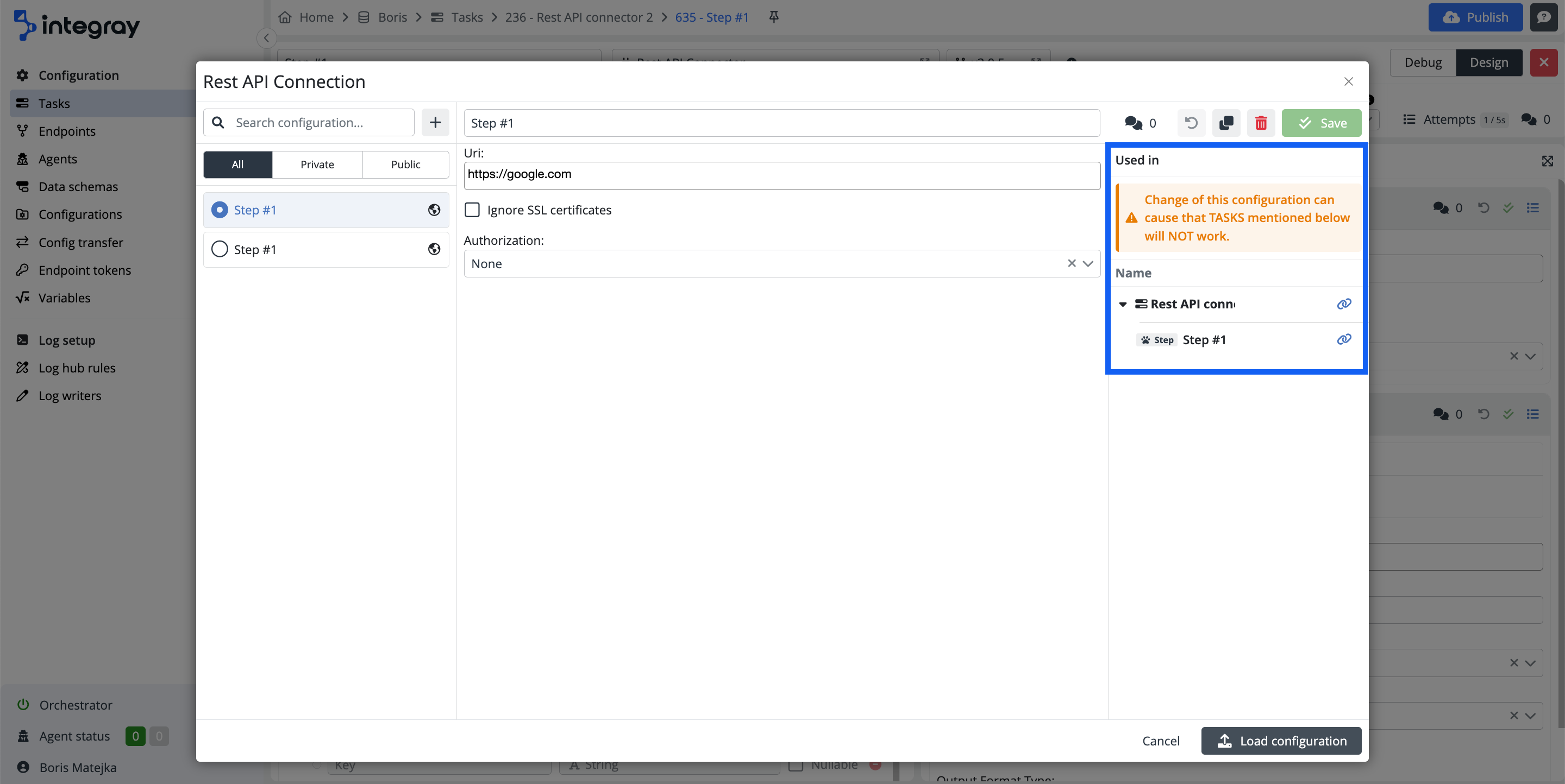
- To show you where the task, and task steps use the existing configurations. The tasks, and task steps, providing the links to navigate you directly to that location opened in a new browser tab.
Edit the configuration
Use the configuration editor to alter/modify existing configuration.
Save the new or altered configurations as private or public
-
Save as private and restrict the configuration to the respective task step only.
-
Save as public and enable the configuration for broad use across the tasks of the entire Company.
The system intelligently assists you in deciding whether to save your configurations as private or public, depending on the type of connector used. This feature enhances your efficiency by suggesting the most suitable storage option based on the nature of the configuration and its potential reusability.
For instance, when using the MS SQL connector, the system may recommend saving the configuration schema, which includes the connection string, as public. This is because the connection string is a generic component you will likely reuse across multiple tasks. On the other hand, the system will suggest saving these as private for specific SQL scripts that include Data Checkpoint definitions. Such scripts are typically tailored to individual tasks and are less likely to be reused, making private storage the more appropriate choice.
Here, you can find a table that presents an inventory of connectors, their respective configurations, and the default settings designated as private or public for storing these configurations.
Practical recommendation
- If you have a connection string to the database you use on other tasks as well, then make sure you save it as public.
- If you have specific SQL or JS or other code valid only for the single step, then make sure you save it as private. You would unlikely reuse the same code in any other task.
- If you have RestAPI connection configuration (URL and authorization),save it as public, as it's very likely you'll reuse this in other tasks.
- On the other hand, you should save your RestAPI Endpoint and payload definition as private due to its specifics for the individual task.
Replace current configuration with any other available
Select and replace the currect configuratrion with another available configuration for the connector in the task step.
-
Deactivate configuration - Deactivate obsolete configuration.
-
Create and add new configuration - Create a new configuration for the connector.
Connector without configurations
No configuration sections is available for this type of connectors. The connector has all necessary configurations hard coded inside with no need of additional user input. The right side of the task step editor is empty.
Example: YAML to JSON connector
No configuration expected. The connector has the requrired input and output schemas, and input mapping, nevertheless it is not allowed to further modify the data within this connector.
